
Stienman's stuff
- Thread starter strawman
- Start date
More options
Export threadA local neurosurgeon commissioned a custom thermal grill so he can see if it can replace more expensive non damaging pain devices for pain neural pathway studies. Should be done next week, here's what it looks like:
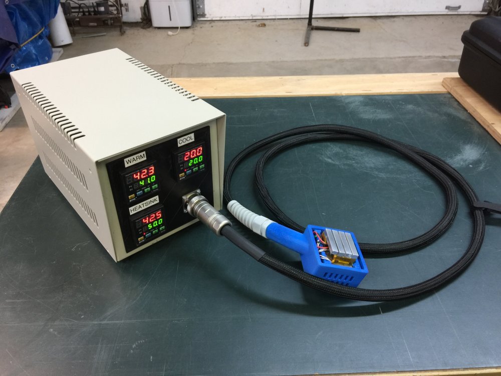
The head is 3D printed and the metal pieces are custom milled on my tiny hand controlled milling machine. Had a huge learning curve, and went several times over my original estimated time (fixed bid, though, so I earned experience more than money due to my poor estimation skills), and so I'm glad it's nearly done, and even happier that it works as well as the previous thermal grill I made.
The plastic head is a single 3D printed part with a floating cage inside that holds the grill. The floating is accomplished with springs built into the design so that pressure sensors can tell how much pressure is being used to hold the grill against the test subject's skin.
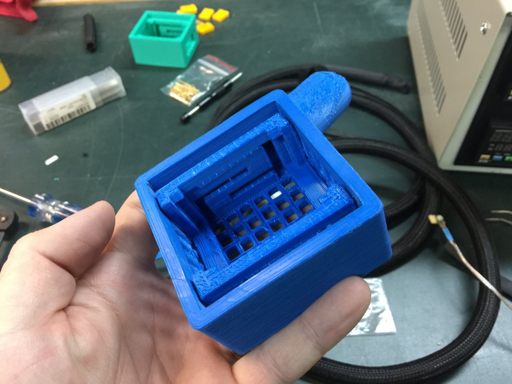
AFAIK it takes some effort to get acetone baths to perform consistently and evenly. If he was producing many of these it might be worth the R&D time/effort/materials, otherwise he's just introducing a bunch of variance (requiring extra design tolerance) into all the pieces.Is it worth finishing with acetone vapor, or would that throw off the strain gauge too much (or destroy the part!)?
--Patrick
Nope:Is it worth finishing with acetone vapor, or would that throw off the strain gauge too much (or destroy the part!)?
--Patrick
- They're fine with the finish (increases grip anyway)
- It would take a lot more time, which I've already overspent
- If I make a mistake printing another one and cleaning the supports out along with some internal sanding so the carrier moves smoothly takes 6 or more hours, so I'm not keen on learning how to do the acetone vapor smoothing when the cost of making a mistake is so high.
I did use some flame heat (propane touch) to smooth a little bit of it, and eventually I'll play with acetone vapor smoothing, but not for this project.
I do have several prints that I can't use so I have test pieces when I decide to experiment.
I'm using force sensing resistors, not sure if they'd withstand acetone (I doubt it though) but if I were to do any post processing I'd do it with nothing else installed anyway.
Yes and no. I will eventually set up a chamber for smoothing and if I was already experienced with the process I would have simply included it as part of my iterative design. I printed 3 carriers before I designed the enclosure, then printed 2 of those before I was happy with it, then printed 3 more to find the best orientation on the printer (combination of support and adhesion issues led to warping, and my new printer doesn't have a heated, draft free enclosure like the old one did, so the problems were troublesome.)AFAIK it takes some effort to get acetone baths to perform consistently and evenly. If he was producing many of these it might be worth the R&D time/effort/materials, otherwise he's just introducing a bunch of variance (requiring extra design tolerance) into all the pieces.
So once I have a method and equipment set up then I don't think I'd have any issue with doing it for one-off projects like this.
As neat as this looks I still have a long way to go anyway. There are issues I still had at the end which won't affect use or operation, but should be improved on. For instance the printer is set up to over-extrude slightly, which helps layer adhesion, but messes with the build size, further ABS shrinks when it cools and I didn't account for that. I made the model fully parametric (in OpenScad for the curious - I did the prototype in fusion 360, but I'm a programmer at heart) so through iterative design I just accounted for any minor issues by adjusting the variables, but need to be able to create parts that are better than the current +/- .25mm accuracy I believe I'm currently getting. That's just too much variance for a lot of work that interfaces with other components.[DOUBLEPOST=1485542281,1485542207][/DOUBLEPOST]Oh, another reason not to finish it: The client is really excited about 3D printing and making it look like an injection molded part would actually be disappointing to them, since they intend to show it around and emphasize the 3D printed part.
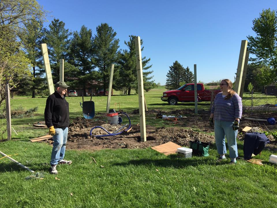
I've been wanting a good, large structure for a tire swing for some time now, so I've recently been noodling over the design and costs. My dad said he'd be visiting this previous week, and he asked if there was a project he could help with, since we tend to bond over building things. So I put the tire swing project on the fast track and we built this:
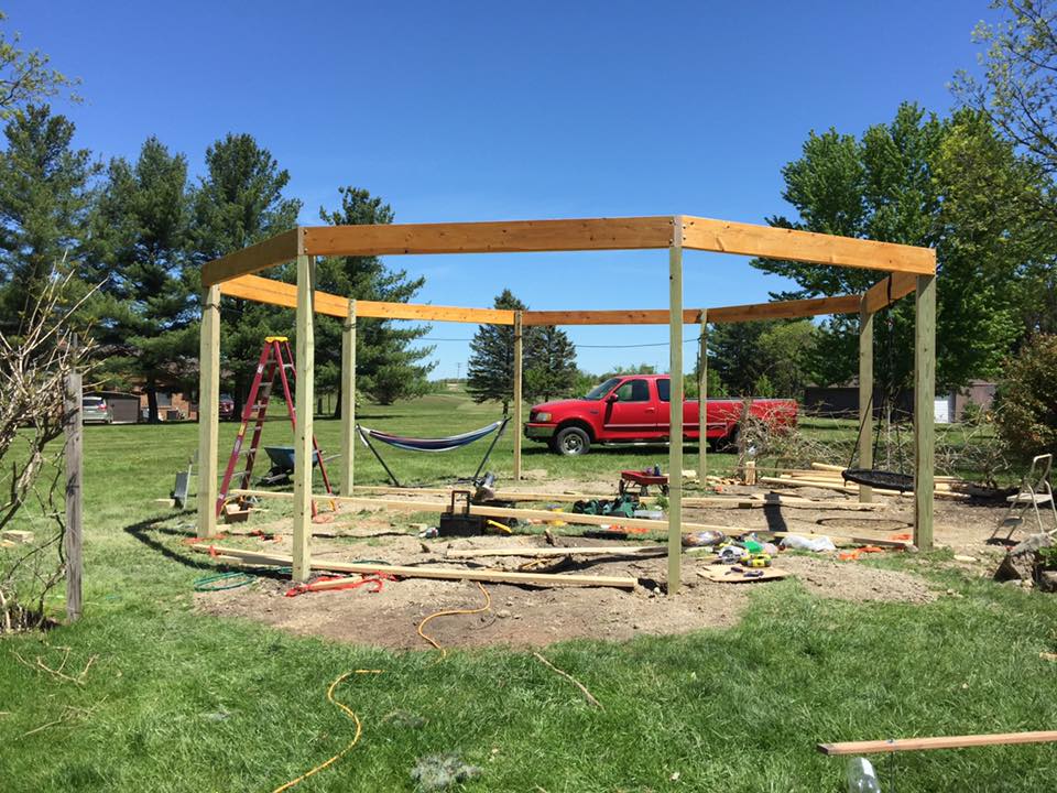
It's essentially an octagon, but two side opposite each other are 12 feet long, while the other six sides are only 10 feet long. The two twelve foot wide sides are for swings that go in all directions (aka, tire swings), as long as they only hang 6-7 feet from the top beam. So we have room for a tire swing, and a ring/net swing (already in place on the right). We will leave one side open, so the remaining five will be filled with other swings of various kinds. Probably a few bench swings, a few hammocks. Maybe we'll outfit one as a picnic table (that probably won't swing... probably). We intend to have multiple fasteners in each space (eventually) so we can reconfigure it as needed. So all hammocks for sleeping outside in the summer, or all picnic tables for a party, for instance. Would be interesting to make a double bench swing that faces each other with a table in the middle, but I'm guessing that would be strange.
The large bays use two 6x6 (140mm square cross section) treated posts each, with 4x6 posts for the remaining four posts, and all the posts go 4 feet (1.2m) in the ground with a suitable amount of concrete below and around the bottom of the post. The posts are notched so the headers rest on top of the notches and bolt into the posts. We will be adding some additional beams across top so the posts share side loads better, and the posts and a few other bits need more wood stain so it all matches the header color.
Eventually we'd like to put some sort of roof over it, but that's going to have to wait, at least until we can afford to fill it with swings. We will almost certainly have a fire pit in the middle.
We did run into one electrical wire during digging, but we're fairly certain it's an unused wire for a pool the previous owners had (only 12awg) , and I believe I've already located its termination inside the house (which was cut in a crawlspace) so I wired up an outlet on one of the posts, and if I'm correct then eventually I'll connect the cut wire in the house and have electricity out there.
Here's the area the morning after digging the holes. We rented a little stand-on mini skid steer with a 16" (40cm) diameter auger on it. By the time I got to the eighth hole I was able to do it in under 15 minutes. They have to be deeper than 4 feet (1.2m) to avoid the effects of frost heaving. Here in southern Michigan it's possible for the ground to freeze up to 42" deep, and if there's water under a structure, the freezing water may push structures out of the ground. So while I wanted deep holes to provide good support anyway, they needed to be this deep so none of the posts would be pushed out of the ground slowly over several winters.
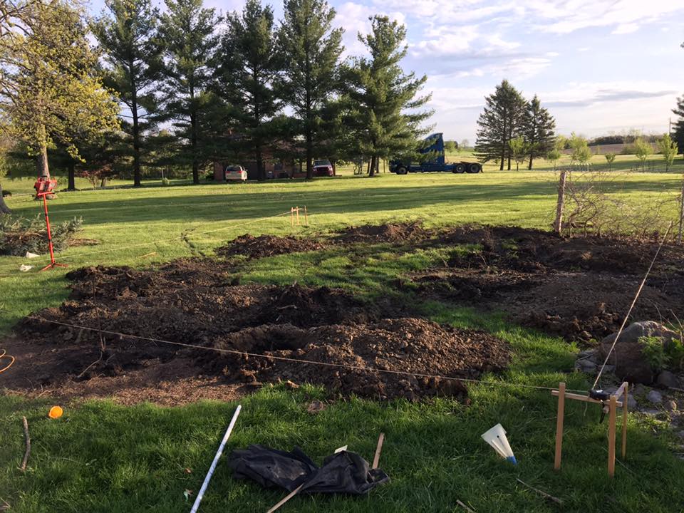
Below you'll see the water that collected in them overnight (mostly groundwater), and consistency of the soil (all clay), and the cut wire almost in the middle of the hole.
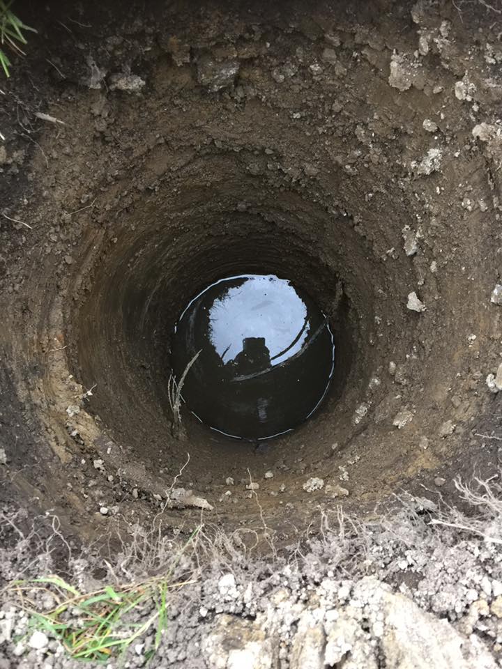
That day we put 1 bag of concrete in the bottom of each hole, creating thick pads for the posts to rest on, preventing them from snicking into the ground. The following day we put the posts in, spaced them apart, plumbed them straight, poured another bag's worth of concrete in the bottom to hold each post down (the posts had screws in the bottom to embed them firmly into the concrete), and then fill the remainder of the holes with dirt.
We built a support structure around the middle to keep everything in place when we were pouring concrete, and left it there so we could stand on it while preparing the tops of the posts to receive the headers.
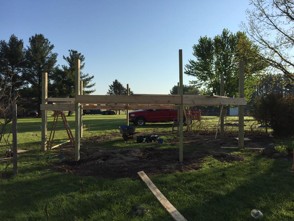
I didn't think through how I was going to notch the posts and connect the headers, so I spent nearly half a day working it out, and when we were planning the location of the set it took us over half a day to figure out where it was going to be and how it was going to be oriented. Reached a stalemate, in fact, until I realized we could take down a pine tree, then suddenly everything fell into place. This was supposed to be a 3 day project, but we finished it up this morning after about 5 days of work.
Learned a lot, would do a few things differently if I had to do it over. Still lots of little things to do - attach the swings, level and grass the area, put in a fire pit, etc, etc, etc. But the major portions are done and the rest can be done in little 1-2 hour projects here and there.
Lots of fun, but glad it's done![DOUBLEPOST=1494876210,1494875986][/DOUBLEPOST]Oh, and for those wondering, frost heaving is why basements are more common up north than in the south. If you have to dig a foundation 4 feet down to avoid frost heave, you might as well dig another 4 feet and have a basement. The cost isn't that much more.
It's essentially an octagon, but two side opposite each other are 12 feet long, while the other six sides are only 10 feet long. The two twelve foot wide sides are for swings that go in all directions (aka, tire swings), as long as they only hang 6-7 feet from the top beam. So we have room for a tire swing, and a ring/net swing (already in place on the right). We will leave one side open, so the remaining five will be filled with other swings of various kinds. Probably a few bench swings, a few hammocks. Maybe we'll outfit one as a picnic table (that probably won't swing... probably). We intend to have multiple fasteners in each space (eventually) so we can reconfigure it as needed. So all hammocks for sleeping outside in the summer, or all picnic tables for a party, for instance. Would be interesting to make a double bench swing that faces each other with a table in the middle, but I'm guessing that would be strange.
The large bays use two 6x6 (140mm square cross section) treated posts each, with 4x6 posts for the remaining four posts, and all the posts go 4 feet (1.2m) in the ground with a suitable amount of concrete below and around the bottom of the post. The posts are notched so the headers rest on top of the notches and bolt into the posts. We will be adding some additional beams across top so the posts share side loads better, and the posts and a few other bits need more wood stain so it all matches the header color.
Eventually we'd like to put some sort of roof over it, but that's going to have to wait, at least until we can afford to fill it with swings. We will almost certainly have a fire pit in the middle.
We did run into one electrical wire during digging, but we're fairly certain it's an unused wire for a pool the previous owners had (only 12awg) , and I believe I've already located its termination inside the house (which was cut in a crawlspace) so I wired up an outlet on one of the posts, and if I'm correct then eventually I'll connect the cut wire in the house and have electricity out there.
Here's the area the morning after digging the holes. We rented a little stand-on mini skid steer with a 16" (40cm) diameter auger on it. By the time I got to the eighth hole I was able to do it in under 15 minutes. They have to be deeper than 4 feet (1.2m) to avoid the effects of frost heaving. Here in southern Michigan it's possible for the ground to freeze up to 42" deep, and if there's water under a structure, the freezing water may push structures out of the ground. So while I wanted deep holes to provide good support anyway, they needed to be this deep so none of the posts would be pushed out of the ground slowly over several winters.
Below you'll see the water that collected in them overnight (mostly groundwater), and consistency of the soil (all clay), and the cut wire almost in the middle of the hole.
That day we put 1 bag of concrete in the bottom of each hole, creating thick pads for the posts to rest on, preventing them from snicking into the ground. The following day we put the posts in, spaced them apart, plumbed them straight, poured another bag's worth of concrete in the bottom to hold each post down (the posts had screws in the bottom to embed them firmly into the concrete), and then fill the remainder of the holes with dirt.
We built a support structure around the middle to keep everything in place when we were pouring concrete, and left it there so we could stand on it while preparing the tops of the posts to receive the headers.
I didn't think through how I was going to notch the posts and connect the headers, so I spent nearly half a day working it out, and when we were planning the location of the set it took us over half a day to figure out where it was going to be and how it was going to be oriented. Reached a stalemate, in fact, until I realized we could take down a pine tree, then suddenly everything fell into place. This was supposed to be a 3 day project, but we finished it up this morning after about 5 days of work.
Learned a lot, would do a few things differently if I had to do it over. Still lots of little things to do - attach the swings, level and grass the area, put in a fire pit, etc, etc, etc. But the major portions are done and the rest can be done in little 1-2 hour projects here and there.
Lots of fun, but glad it's done![DOUBLEPOST=1494876210,1494875986][/DOUBLEPOST]Oh, and for those wondering, frost heaving is why basements are more common up north than in the south. If you have to dig a foundation 4 feet down to avoid frost heave, you might as well dig another 4 feet and have a basement. The cost isn't that much more.
Shouldn't be too much more work to add a bi-level vented roof to the structure, you think? That'd keep it from being ripped off by the wind but still provide shelter for whatever you have going on below (and a place for the firepit to vent smoke, besides).
--Patrick
--Patrick
You aren't going to put solar tiles on a swing set are you? >.>My wife is already trying to get me to work on a roofing solution, and that's definitely one of the contenders. Cost is higher, but there are many benefits.
I need to run a gofundme for this...")
Well, if he did, he wouldn't have to run the electric out there for the fans, now would he?You aren't going to put solar tiles on a swing set are you? >.>
--Patrick
Oof, no, those are uselessly expensive! We probably won't mount solar anything on this, but it's an option we aren't ruling out.You aren't going to put solar tiles on a swing set are you? >.>
So I found a free 56 foot antenna tower on Craigslist, and took it home.
Had to disassemble it first, though.
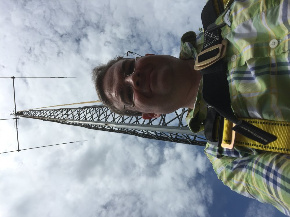
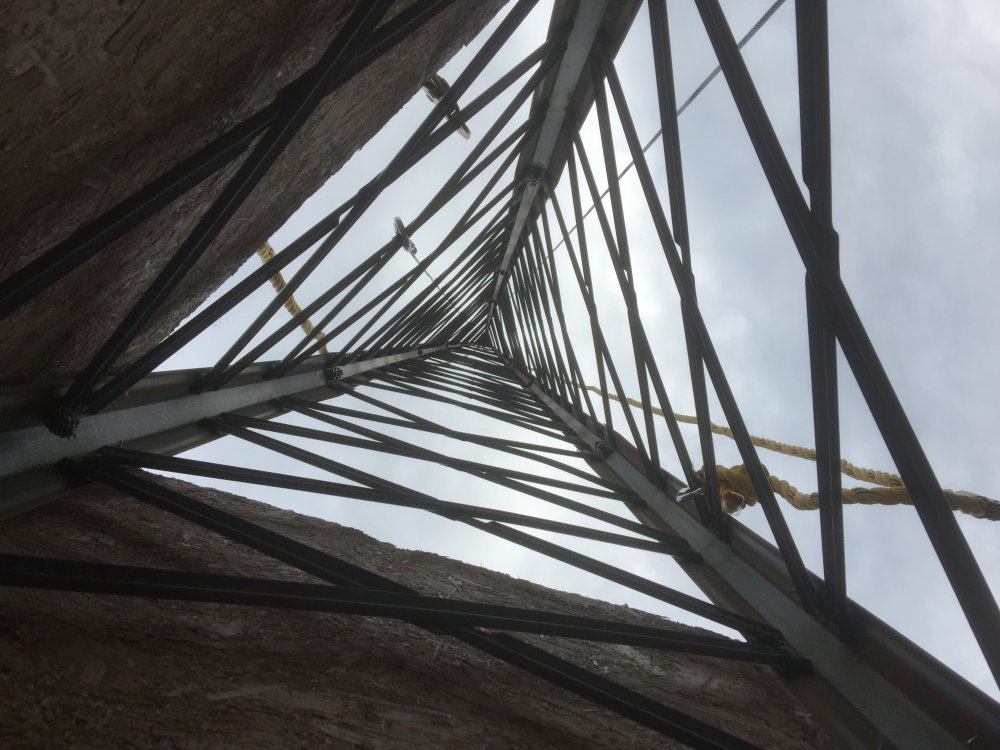
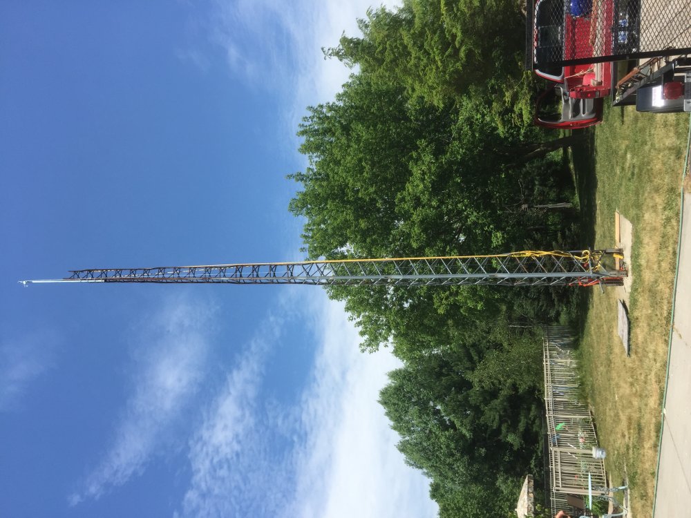
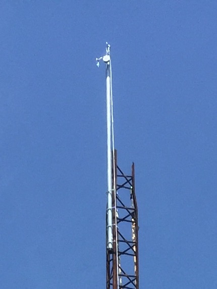
After removing two antennas and three 8 foot sections I opted to tilt the remaining 32 feet over and disassemble on the ground:
Lots of work, but I got about $1,000 worth of ham radio antennas and a rotor, as well as the $1,700 tower for about $500 for the tools and materials I bought to take it down. Plus the 20 hours it took to do so.
It'll cost more in materials, permits, and repainting to put it back up on my property, but I expect it'll still be an overall savings and hopefully down the road I can use it to get real high speed internet wirelessly.
Had to disassemble it first, though.
After removing two antennas and three 8 foot sections I opted to tilt the remaining 32 feet over and disassemble on the ground:
Lots of work, but I got about $1,000 worth of ham radio antennas and a rotor, as well as the $1,700 tower for about $500 for the tools and materials I bought to take it down. Plus the 20 hours it took to do so.
It'll cost more in materials, permits, and repainting to put it back up on my property, but I expect it'll still be an overall savings and hopefully down the road I can use it to get real high speed internet wirelessly.
No, it's not strong enough for that. Maybe a small one, but it can only support a 20-30 square foot wind load up to 80mph winds, so it's a no go for wind energy.Goodness, but you have an active project life.
Now, are you going to attach some guy-wires and mount a windmill on the top, too?
--Patrick
That's why I suggested the guy-wires, because I assume they would up the wind load tolerance.No, it's not strong enough for that. Maybe a small one, but it can only support a 20-30 square foot wind load up to 80mph winds, so it's a no go for wind energy.
--Patrick
Ah. I suppose I could beef it up, but guy wires are very annoying, and they'd buy me maybe a few hundred watts additional of intermittent power.That's why I suggested the guy-wires, because I assume they would up the wind load tolerance.
--Patrick
Well, if you need another one, let me know. I think my father still has the pieces of his from when he ran a taxi company. No idea what sort of condition they're in, since the segments have been stacked up lengthwise on the ground for who knows how long, but y'know...potentially free.
--Patrick
--Patrick
I am interested. I'm going to need another one at the end of the potential internet link, so if you wouldn't mind asking him about the size or make/model there's a possibility I'd make the trek to get it and put it to use.Well, if you need another one, let me know. I think my father still has the pieces of his from when he ran a taxi company. No idea what sort of condition they're in, since the segments have been stacked up lengthwise on the ground for who knows how long, but y'know...potentially free.
--Patrick
I'm visiting tomorrow, I'll ask.I am interested. I'm going to need another one at the end of the potential internet link, so if you wouldn't mind asking him about the size or make/model there's a possibility I'd make the trek to get it and put it to use.
--Patrick
The company I work for makes mouthguards for sports. They're having a sale for a little while, and IIRC some of you play sports (we've even had roller derby players here...) so if you need a mouthguard for yourself or your youth, it might be something worth looking at. 15% off automatically applied in the shopping cart.
http://sisuguard.com
http://sisuguard.com
There are, but it appears they aren't on sale:Are there any models for bruxists? Or are they all athletic?
--Patrick
http://www.sovanightguard.com/
Today I discovered this company. I think you might find some of their stuff interesting, especially with some of yourI'm going to need another one at the end of the potential internet link
https://www.ubnt.com/products/
--Patrick
Last edited:
Yes, they are the first choice should anything come to fruition regarding my internet link. Their prices are very good for what they do.Today I discovered this company. I think you might find some of their stuff interesting, especially with some of your products. And their prices don't look half bad, either.
https://www.ubnt.com/products/
--Patrick
So tell me...how excited should I be?
They're actually up to 5.1, btw, which includes some pretty hefty improvements for "just" a point release.
--Patrick
They're actually up to 5.1, btw, which includes some pretty hefty improvements for "just" a point release.
--Patrick